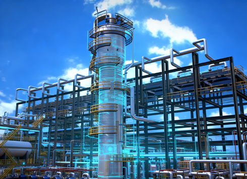





Fire lane looks wide enough in the factory rendering—so why does permit review say the turning radius is insufficient? Could the model have missed the master plan control lines from the start?
In 3D presentations for industrial plant architecture and landscape planning and design, when the fire lane, turning radius, or firefighting operation area does not match the permit submission basis, the problem is usually not rendering but modeling: the model was placed by visual feel, without applying the confirmed master plan, surveyed control lines, and turning radius arcs to the geometry. Based on 2026 industrial park project delivery experience, renderings are only responsible for explaining the scheme clearly; permit conclusions go back to the confirmed drawings and surveyed data. When the two bases diverge, the cost usually shows up as remodeling and re-rendering.
Why does permit review still say the turning radius is insufficient when the lane looks wide enough in the rendering?
Renderings are perspective images, and near-large/far-small naturally exaggerates or compresses width. A lane looking wide in a standard aerial view does not mean the plan clear width and turning radius meet the requirements; reviewers look at a dimensioned general layout plan, not the visual impression.
Another common source is mixing near-term and long-term phases. Factory parks are often built in phases: the current phase only paves part of the site, while drawings follow the long-term master plan. If modeling fills in long-term landscaping and roads, the image diverges from the current phase’s scope.
- Dimensions cannot be measured from the image: Renderings generally have no scale bar or north arrow, so width can only be estimated visually.
- The turning radius is controlled by arcs: It involves the inner radius plus the vehicle swept path; placing the model by eye will not be accurate.
- Firefighting operation areas have clearance requirements: Tree canopies, awnings, light poles, and signage can all obstruct them, and the entourage layer is the easiest to add casually.
- Phasing and long-term plans are inconsistent: Filling the model does not equal current-phase implementation, and the green space ratio and paved area can easily mismatch.
- Vertical elevations are not built into the model: Road surface, landscaping, and curb height differences are only visual, and still need to be recalculated for permit submission.
“Three Layers and One Checklist”: A layered approach to 3D modeling for factory parks
Rework on industrial park projects mostly comes from wrong positional relationships, not from insufficient model detail. Lock the control lines that cannot move first, then layer solids and entourage on top; later changes stay in the outer layers.
- Control line layer: Land-use red line, building outlines, fire lane centerlines, turning radius arcs, green space ratio calculation boundaries, and key elevation control points, based on the confirmed master plan and surveyed data.
- Solid component layer: Main factory buildings, gatehouses, perimeter walls and gates, paved roads, parking lots, loading and unloading areas, and pipe rack supports, with unified units and coordinate origin.
- Entourage and decoration layer: Trees and shrubs, lawns, paving, light fixtures, signage, vehicles, and people, graded by foreground, midground, and background, and replaceable.
- Checklist: A single table records each layer’s data source, version basis, and drawing issue date, delivered to the client with the files.
Before the control line layer is finalized, do not place entourage, or trees and lights will be moved around repeatedly. Use meters as the unified unit and one origin for the solid layer. In the entourage layer, only foreground elements justify detailed models; midground and background can use billboard assets. When the client changes landscaping or paving, usually only the third layer is affected, and it can typically be completed in 1 to 3 working days (experience range). Once the red line, lane, or building outline changes, work must return to the first layer, and the cost rises noticeably.
Three common bottlenecks at delivery: data accuracy, version basis, and schedule
A common situation on projects: the client provides only an early CAD master plan and phone photos from the site, asks for four aerial views plus two viewpoints within two weeks, and wants the landscaping to look as if it is already built. The constraints are insufficient data accuracy and a green space ratio not yet finalized. The approach is to first lock control lines with the Three Layers and One Checklist method, grade entourage by midground and background, unify tree height and leaf color specification, and hold off on foreground close-ups. The trade-off is that when the green space ratio is later adjusted, the entourage needs one overall rearrangement, adding about 2 to 4 working days (experience range); if the model was filled from the start with guessed green volume, the rework scope is even larger.
A common trade-off when the schedule is tight is to first issue a version with correct control lines and simple materials for the client to confirm positional relationships, then add materials and entourage for final refinement. If entourage is refined first and control lines are checked later, the probability of rework is noticeably higher.
Static renderings, real-time engines, and lightweight web 3D: typical ranges for industrial park projects
The deciding factor is whether the client needs to navigate it themselves. If the need is only a final presentation, a few images, and one animation, the static route is more economical. If they need to walk through it in a meeting room or on a phone and compare options, the real-time route is more suitable. If they only need to view the model remotely, the lightweight web route can be a supplement.
- Static rendering: Typical schedule 5 to 12 working days (experience range). Suitable for scheme presentations, permit submission support, and marketing materials; not suitable for repeated free-viewpoint comparison.
- Real-time engine walkthrough: Typical schedule 2 to 5 weeks (experience range). Suitable for multi-scheme comparison, VR site review, and internal review; requires stricter mesh reduction and material standards.
- Lightweight web or mini-program 3D: Typical schedule 1 to 3 weeks (experience range). Suitable for remote viewing and display; image precision is lower than offline rendering.
- Cost reference: Quotes for similar needs commonly range from a few thousand to tens of thousands of RMB (experience range). Differences mostly come from area, precision, number of viewpoints, whether animation or interaction is included, and optimization work such as mesh reduction and baking.
When reviewing a quote, do not look only at the total price. Check how many images, how many viewpoints, and how many revision rounds are included. Put these three items in the requirement list so quote ranges are comparable.
Where it fits and where it does not
In industrial park projects, 3D presentation is suitable for scheme presentations, bidding and tendering, investment promotion displays, and visual explanations supporting permit submission. It is especially suitable for phased projects that need to explain near-term and long-term relationships clearly, and for aligning structural, municipal, landscaping, and fire protection disciplines on the same basis.
- Not suitable for replacing construction drawings or permit drawings; 3D presentation does not carry approval conclusions.
- Not suitable for precise quantity takeoff or cost estimation; a presentation model is not a quantity takeoff model.
- No need for a real-time engine when the need is only a few final images and one animation; forcing a walkthrough will noticeably extend the schedule.
- Do not force a start with insufficient data: When there is only one hand-drawn sketch and the red line is not fixed, waiting for data is usually more time-efficient than modeling first.
One-sentence boundary: A rendering can show roughly what it will look like, but it cannot prove that metrics comply; metrics must be checked against the confirmed drawings and surveyed data.
FAQ
How long does this kind of 3D presentation for a factory park usually take?
Static renderings typically take 5 to 12 working days (experience range), real-time walkthroughs 2 to 5 weeks, and lightweight web displays 1 to 3 weeks; the number of viewpoints, revision rounds, and data completeness have a noticeable impact.
What drives quote differences, and why do some cost a few thousand while others cost tens of thousands?
Differences mainly come from area, level of detail, number of viewpoints, whether animation or interaction is included, and the amount of mesh reduction and baking optimization; the more complete the data, the closer to the lower end of the range.
Are modeling and rendering done by the same team?
A common approach is for the same team to do both in one continuous process to reduce loss of basis. Splitting them is also possible, but if so, delivery must include all source files, unit specifications, and a material naming list; otherwise the receiving party may rebuild the model.
What formats are usually delivered?
Common deliveries include source files, common 3D formats, and rendering and post-production files. For a walkthrough, the engine project or packaged application is provided separately; for web display, a reduced-poly model and compressed textures are also provided.
If the client changes the green space ratio or paving at the last minute, is the rework significant?
If only the entourage layer changes, the impact is relatively small, typically 1 to 3 working days (experience range). If it affects the red line, lanes, or building outlines, work must return to the control line layer, and the cost rises noticeably.
If your factory park project is stuck because the rendering and permit submission basis do not match, it is advisable to first organize the confirmed master plan, surveyed data, and control lines into one checklist, then decide between static renderings and a real-time walkthrough. When the area is large, phasing is complex, and cross-department comparison is needed, the real-time route saves more communication cost; for pure presentation scenarios, a real-time engine is not necessary. When data is insufficient, gather data first; it is usually more time-efficient than modeling first.
-
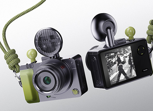 EDC·Trendy Camera Product Design: Form Follows Emotion
EDC Toy Camera: Braun-inspired retro design ...
-
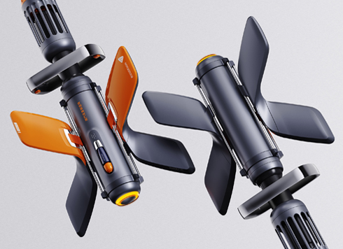 Product Design of Children's "Bubble Rocket" Underwater Thruster
Inspired by "Octonauts + Space", kids' "Bub ...
-
 Design of Adaptive Intelligent High-Altitude Shuttle Transport Robot
Smart rural shuttle bot: Streamlined, weath ...
-
 "Effortless" Exoskeleton Wear: Unleash Ultimate Freedom in the Sea
"Unfelt Wearability" & "Bionic Power" redef ...
-
Why does mini-program 3D start smooth on a budget Android phone but get hot and drop frames after two minutes?
Date: Oct 14, 2026 Read: 7
-
In product demo animation, prototype still frames look premium, but the final video moves like PPT slides—should you add motion previews first or increase render precision?
Date: Oct 13, 2026 Read: 10
-
In web 3D, glass curtain walls and railings flicker at oblique angles—should you merge coplanar geometry first or adjust the camera near/far clipping planes first?
Date: Oct 12, 2026 Read: 18
-
Three.js 3D Animation on a Showroom Touchscreen: Can It Stay Stable for a Full Day Offline Without Restart?
Date: Oct 11, 2026 Read: 25
-
Client says your UE5 render looks like a game screenshot: adjust post-processing first or change the reflection source first?
Date: Oct 10, 2026 Read: 36