





Product Appearance Design Modeling: The Client Only Gives ID Sketches and Competitor Images, and the Render Highlight Band Looks Wrinkled—Can Adjusting Materials Really Fix It?
In product appearance design modeling, when a render shows wrinkled, broken, or rippled highlight bands, it is usually not because the material ball was set wrong or the renderer is inadequate. The cause is usually that surface continuity was not made smooth during modeling—most commonly, adjacent surfaces only achieve positional alignment (G0), not tangent or curvature continuity (G1, G2). In 2026 project delivery experience, the recommended order of judgment is: first inspect the model with zebra stripes and curvature combs, then switch to a neutral gray model for rechecking, and only last suspect the material. High-reflection materials only amplify defects; they do not create wrinkles out of nowhere.
Why a Wrinkled Highlight Band Immediately Reveals a Surface Problem
In product appearance design, a highlight band is essentially a contour line produced when environment reflections are compressed by the surface. Even if surface curvature changes by only a fraction of a millimeter, the highlight band will become thinner, break, or wrinkle at that spot. The human eye is far more sensitive to a continuous highlight band than to outline edges, so when a client says “the highlight is not smooth,” it often points to the problem better than looking at three orthographic views.
By degree of continuity, modeling and engineering commonly use three criteria to describe surface joins; understanding them is necessary to align with client expectations:
- G0 (positional continuity): the boundaries of two surfaces coincide but tangent directions do not match; the highlight band breaks directly here, commonly seen on edges left unprocessed after Boolean operations.
- G1 (tangent continuity): boundary tangent directions match, so the highlight band connects, but the transition “goes from thick to thin,” giving a harder visual feel.
- G2 (curvature continuity): curvature is also continuous, and the highlight band transitions evenly. Products viewed up close, such as consumer electronics housings and automotive exterior trim, are usually required at this level.
These three criteria are not “the higher, the better”; they depend on viewing distance and reflection intensity. If the camera is far away and the material is more matte, G1 is often enough; for close-up shots with metallic paint or mirror finishes, G2 is what keeps flaws from being called out.
First Decide Whether It Is a Model Problem or a Material Problem: Three Looks and One Swap
Getting the judgment order wrong can lead to a long time spent changing the wrong thing. A common situation on projects is that the client says the highlight is wrinkled, so the modeler adjusts roughness and changes the environment map, and after several rounds the problem remains—because the root cause is in the model. You can self-check in this order:
- Look at zebra stripes: apply a black-and-white striped reflection environment to the model. Places where the stripes distort, break, or lock up are basically surface problems.
- Look at the curvature comb: inspect whether the curvature comb is smooth on key cross-sections. Sharp points or jagged edges indicate discontinuity in curvature.
- Look at isoparms: uneven topology or sudden spacing changes often mark hidden trouble spots left by subdivision or patched surfaces.
- Swap to a neutral gray model: temporarily remove textures and color, and look again with a single gray high-reflection material to rule out interference from materials and textures.
What counts as passing: in the gray model state, the highlight band is continuous from the main viewing angles, its width changes gently, and zebra stripes neither break nor knot. Then you can move on to applying materials. If the gray model itself is already wrinkled, do not touch the material first; changing materials cannot cure it.
The Surface Control Process for Product Appearance Design Modeling
Appearance surfaces are rarely right the first time. From experience, the work can be broken into a five-step chain. Changes earlier in the chain cost less; later changes cost more, so the order cannot be reversed.
- Sketches set the skeleton: first convert the front, side, and top views or the ID sketch outlines into reference lines and key cross-sections, confirming proportions and main transition locations.
- Lay out large surfaces smoothly: build the main body surfaces with as few patches as possible, prioritizing continuity on the primary viewing surface and the areas the highlight passes through. Do not subdivide too early.
- Close edges with fillets: determine fillet radii for parting lines, button grooves, and corners according to viewing distance. For close-up parts, an experience range from a fraction of a millimeter to a few millimeters is common, adjusted to product size.
- Verify highlights: in the gray model state, run through zebra stripes and curvature combs, focusing on the surfaces the main highlight band passes through.
- Recheck in render: after applying materials, render from the final viewing angles and confirm the highlight has not produced new breaks.
Common rework causes cluster in two places: first, subdividing before going back to patch large surfaces, which means that if you later want to adjust curvature, you have to rebuild; second, fillet radii and parting lines are not fixed during modeling and are changed only at render or structural stage, affecting the whole model. On the toolchain, according to common 2026 practice, industrial appearance work often uses NURBS tools for Class-A surfaces, then polygon tools for presentation-level models and rendering; if only presentation renders are needed, the polygon subdivision path is usually faster. Which path to choose depends on whether the model will later be handed to structural work.
On Delivery: How Highlight Band Rework Usually Happens
A common situation on projects: the client gives only one ID sketch and a few competitor reference images, the schedule is compressed to five to eight working days (typical range), and the material requirement is metallic paint plus clear coat. If you go straight to metallic material rendering, then after the client sees the wrinkled highlight at a corner and asks for changes, you often need to rebuild two or three patches, rerun the render, and pay the price of two to three days of rework plus a schedule slip. In project delivery practice, it is better to run zebra stripes once at the gray model stage before applying materials, costing about half a day more, and then there is basically no rework afterward. Before delivery, check three places first—the surfaces the main highlight band passes through, the fillet transitions, and the parting line positions. These three are the most prone to problems.
How to Choose Between Two Common Modeling Paths
In product appearance design modeling, there are two common paths. It is not about which is better, but about use and the downstream handoff:
- Path A: NURBS / Class-A surface modeling
- Surface continuity: controllable, convenient for achieving G1 and G2
- Revision flexibility: can adjust surfaces locally, but the skill threshold is higher for complex forms
- Experience range: for medium-complexity appearance parts, about 5–15 working days (experience range)
- Best for: models to be handed to structural work, close-up viewing, metal or mirror materials
- Path B: Polygon subdivision modeling
- Surface continuity: controlled by topology and subdivision levels; curvature transitions are less precise than Class-A surfaces
- Revision flexibility: fast for pulling and dragging points, suitable when the form is still diverging
- Experience range: for medium complexity, about 3–8 working days (experience range)
- Best for: presentation renders, demo animations, polygon assets that do not need to be delivered for structural work
The judgment can be simplified: will the model be passed to someone else to continue using? Is the viewing distance close? Is the material highly reflective? If all three answers are “yes,” lean toward Class-A surface criteria; if it is only for presentation renders, Path B is usually faster and more cost-effective.
Applicable Scenarios and Boundaries
This highlight band inspection method suits products where appearance is directly tied to viewing experience—consumer electronics, small home appliances, daily necessities, automotive interior and exterior trim, and products using metal or mirror materials. In these projects, whether surfaces are smooth directly affects how the client perceives product quality, and it is worth spending extra time in modeling.
The applicable boundaries should also be stated clearly: not every product appearance design 3D project is worth taking to G2. If the camera is distant, the product is matte or fabric, or the model is only for internal structural verification and exploded-view diagrams, G1 or even G0 with reasonable fillets is enough. Chasing curvature continuity only lengthens the schedule and increases cost. Likewise, if the delivery purpose is just a few presentation images and the model will not go into structural work, there is no need to accept it under Class-A surface criteria.
Frequently Asked Questions
How long does product appearance design 3D modeling usually take?
Based on 2026 delivery experience, medium-complexity appearance modeling for a single product takes about 3–15 working days, depending on surface precision requirements and whether it needs to be handed to structural work; rendering adds another 1–3 days.
Does a wrinkled highlight band always mean the model must be rebuilt?
Not necessarily. If it is only a local curvature jump left by a fillet or patched surface, local rebuilding is usually enough; if the large surfaces themselves lack continuity, local repair will cause new problems elsewhere.
Are modeling and rendering quoted separately?
Usually yes: modeling is priced by surface precision and number of parts, while rendering is priced by number of images, resolution, and whether animation is included. From experience, the two account for fairly similar shares of total cost, depending on the project.
How smooth do surfaces need to be to count as passing?
The criterion is that, from the final viewing angles, the gray model highlight band is continuous with no breaks or lock-up, and zebra stripes do not knot. For close-up metal materials, checking against curvature continuity criteria is recommended.
What format is usually delivered downstream?
It depends on use: for structural work, neutral formats such as STEP are common; for rendering or animation, polygon formats with materials are common. Before delivery, confirm units and coordinates, and follow the recipient's specifications.
If this version of the model will continue to have its appearance revised, or will later go into structural work, it is recommended to run through the highlight band at the gray model stage before deciding whether to apply materials; for projects that only need a few presentation images and use more matte materials, there is no need to require the higher curvature continuity standard. Clarify the delivery purpose and viewing distance first, then decide how far to take surface quality. This usually saves more time than reworking afterward.
-
 EDC·Trendy Camera Product Design: Form Follows Emotion
EDC Toy Camera: Braun-inspired retro design ...
-
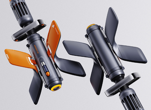 Product Design of Children's "Bubble Rocket" Underwater Thruster
Inspired by "Octonauts + Space", kids' "Bub ...
-
 Design of Adaptive Intelligent High-Altitude Shuttle Transport Robot
Smart rural shuttle bot: Streamlined, weath ...
-
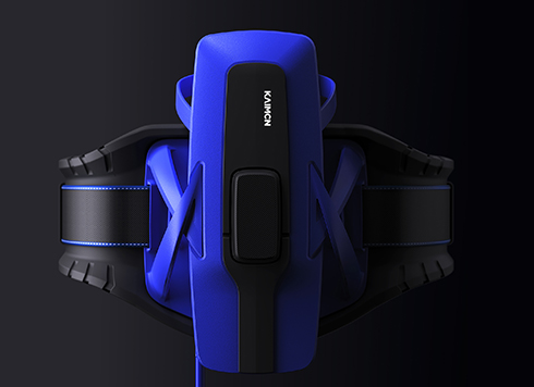 "Effortless" Exoskeleton Wear: Unleash Ultimate Freedom in the Sea
"Unfelt Wearability" & "Bionic Power" redef ...
-
Why does mini-program 3D start smooth on a budget Android phone but get hot and drop frames after two minutes?
Date: Oct 14, 2026 Read: 7
-
In product demo animation, prototype still frames look premium, but the final video moves like PPT slides—should you add motion previews first or increase render precision?
Date: Oct 13, 2026 Read: 10
-
In web 3D, glass curtain walls and railings flicker at oblique angles—should you merge coplanar geometry first or adjust the camera near/far clipping planes first?
Date: Oct 12, 2026 Read: 19
-
Three.js 3D Animation on a Showroom Touchscreen: Can It Stay Stable for a Full Day Offline Without Restart?
Date: Oct 11, 2026 Read: 25
-
Client says your UE5 render looks like a game screenshot: adjust post-processing first or change the reflection source first?
Date: Oct 10, 2026 Read: 36