





When the CAD site plan and site photos don't match for factory landscape 3D modeling, which source should drive the model to avoid rework?
Opening conclusion: When building a 3D model for factory architectural landscape planning and design, if the client's CAD site plan and site photos don't match, the usual answer isn't to pick one — it's to take values by layer: structural-level information such as building footprints, road alignment, and site vertical elevations follows the confirmed drawing version plus measured data; surface-level information such as planting clusters, paving textures, and landscape furniture follows recent site photos and design intent. Based on 2026 project delivery experience, teams that skip this layer judgment and start modeling immediately tend to see rework concentrated in building position offsets and mismatched road interfaces, typically adding about 1 to 3 working days.
Why factory landscape drawings and the site so often don't match
For factory projects, there is often a construction phase, a retrofit, or equipment installation between project initiation and 3D presentation. The CAD the client holds may be a permit-application version or an early version, while the site has already been paved, used for material storage, or fitted with added pipe racks — this kind of difference is normal. Under 2026 delivery practice, judging first whether the difference is structural-level or surface-level, then deciding which source governs, is more efficient than arguing about whose data wins.
Common sources of difference: lagging drawing versions, accumulated construction deviation, temporary facility interference, later modifications. Judgment criteria: anything affecting building footprints, site vertical elevations, or road alignment is structural-level and must be checked first; anything affecting only paving textures, planting clusters, or landscape furniture is surface-level and can be filled in with photos and intent images without overturning the whole model.
Set the baseline first: drawings for structural level, photos for surface level
A common project practice is to rank available materials into four reliability layers and take from the bottom up. When two sources conflict, the layer explains the choice, and the delivery note can state the basis for each value.
- Measured data layer: on-site measured dimensions, control point coordinates, drone orthophotos. Used to correct building spacing, road widths, and site boundaries.
- Structural drawing layer: site plans, individual building drawings, and vertical drawings with confirmed version numbers and issue dates, used to determine building height, number of floors, and road turning points.
- Surface photo layer: recent real-scene photos and videos, used for materials, color variation, current planting, and equipment placement — not for measuring dimensions.
- Design intent layer: client verbal notes, reference intent images, style positioning, used to fill in visual requirements the drawings don't express.
Two cautions when using this: keep a trace for each layer's source — screenshots, file versions, shooting dates recorded in the delivery notes; measured data takes priority over drawings, but only for structure — don't measure building depth from a phone photo, since perspective distortion will skew proportions, which is a high-incidence rework point.
The cost comparison of three routes: follow drawings, follow the site, or compromise
Reducing the question to CAD versus photos ignores the middle route. Based on 2026 project delivery experience, most factory landscape 3D projects take the compromise path. The rough costs of the three routes:
- Route A, CAD governs: suits approval presentations that need consistency with the planning position. The cost is that areas already changed on site will be flagged by the client; partial redo commonly adds about 1 to 2 working days.
- Route B, site photos govern: suits as-built retrofit or construction briefing presentations. The cost is that photo perspective easily distorts road and building proportions, and if it later fails to match the drawings, the whole scene may need redoing.
- Compromise route, structural from drawings, surface from photos: suits most factory park scheme presentations. Experience shows it reduces rework from full-scene rebuild to local replacement, commonly saving about 1 to 3 working days per round.
When choosing, first ask the client one question: who is this version for? For a planning department, alignment with drawings matters; for internal decision-makers, on-site realism matters more. That answer basically settles the route.
On the delivery floor: the cost of one unchecked vertical elevation
A common situation in projects: the client provides only a PDF site plan and a few phone photos, has a limited budget, and needs drawings within ten working days. A steadier approach is to convert the PDF into a reference base map, supplement it with a set of drone orthophotos for position correction, then block out building volumes first; place planting by photo density, and handle materials uniformly at the rendering stage to avoid repeated color tuning slowing down modeling. For this kind of project, the typical experience range from modeling to final images is commonly 5 to 10 working days, with incremental revisions around 1 to 3 working days.
In one similar factory park project, the first version didn't check site vertical elevations; after delivery it was pointed out that the park ground level sat one step above the external road, and the vehicle access ramp was drawn in reverse. The result was two extra days spent fixing the verticals, re-placing planting, and re-rendering — a typical cost of not checking structural-level information first. Since then, deliveries start with a checklist pass over verticals and road openings. The cost is half a day of checking; the benefit is one fewer full-round rework.
Acceptance criteria and applicable boundaries
Acceptance should follow a checkable list, not just whether the image looks good. On dimensional criteria: building length and width, road width, and planting strip width match the confirmed drawings; key dimensions allow common experience deviation but must be recorded; units and coordinates are unified in meters with a single coordinate origin, making later professional software integration easier. On material layers: near-view main roads and building facades have clear materials; distant background elements may be simplified but must not show obvious color-block breaks. On camera views: aerial, eye-level, and local node shots are provided as required, with camera height and focal length suited to the presentation purpose. Deliverables include source files, final images, and documentation; UE5 projects also deliver an engineering package or packaged build with the engine version noted. Rework reasons cluster around: road and building interfaces not matching, inconsistent planting season and tree form between versions, incorrect site elevation benchmarks, overly bright material reflection making the image look washed out, and delivering only final images without source files, which blocks secondary edits. The first four are production-standard issues; the fifth is a delivery-agreement issue, so the delivery format is best written into the confirmation sheet at the quotation stage.
Applicable scenarios: new factory park scheme presentations, retrofit and expansion approval, park investment promotion, landscape scheme review, and pre-construction briefing. Its value is turning lines on a site plan into understandable spatial relationships, so non-specialists can judge road width, building height, and planting density. Not applicable boundaries: if only a flat colored plan or colored site plan is needed, 3D is a misallocation of resources; if the work covers only a single planting strip or small node, 2D drawings plus intent images are usually enough; if there is no spatial dispute and only pipeline routing needs explaining, high-precision modeling isn't needed either. If differences appear only in planting clusters and paving textures, there's no need to overturn the whole model — local replacement is enough; only when building footprints, road alignment, or site verticals conflict does the baseline need to be reset.
FAQ
The client only provided a PDF site plan, no CAD source file — can we still model?
Yes, but first calibrate the PDF scale using known dimensions, then supplement with site photos or satellite base maps for position correction; otherwise building spacing and road widths tend to skew overall.
If the site and drawings don't match, will the cost increase?
It depends on the layer. Surface-level planting and paving adjustments are usually within normal revision scope; structural-level vertical or road rework is incremental work, so revision rounds are best agreed in the confirmation sheet.
What formats are typically delivered for factory landscape renderings?
Common deliverables include JPG or PNG final images, source files, and optional animation video; UE5 projects also deliver a packaged project with the engine version noted, making handover easier.
For presentation-only renderings, how detailed does the model need to be?
It depends on viewing distance and camera. Eye-level close views need clear building facades, paving, and main planting; distant aerial views can simplify background elements, avoiding budget spent on details nobody sees.
Should modeling and rendering be done by the same team or separate teams?
For small and mid-size projects, one pipeline is common — polygon count and material layers are controlled for rendering needs during modeling. For large scenes or parallel work, teams split, but they need to share one unit system and material naming convention.
If you're currently stuck between the drawings and the site materials, start by separating structural level from surface level with the four-layer method, then decide the modeling baseline. It suits factory projects that need spatial judgment and presentation. If you only need a flat colored plan or a single node explanation, 2D materials are usually enough — there's no need to pay extra for 3D.
-
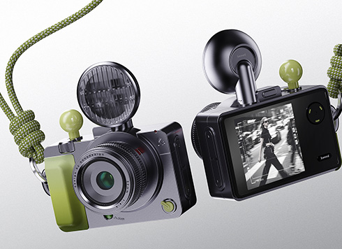 EDC·Trendy Camera Product Design: Form Follows Emotion
EDC Toy Camera: Braun-inspired retro design ...
-
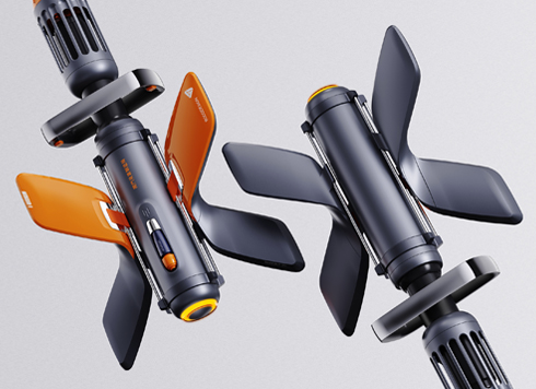 Product Design of Children's "Bubble Rocket" Underwater Thruster
Inspired by "Octonauts + Space", kids' "Bub ...
-
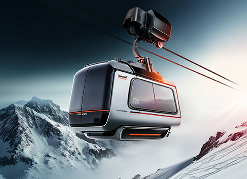 Design of Adaptive Intelligent High-Altitude Shuttle Transport Robot
Smart rural shuttle bot: Streamlined, weath ...
-
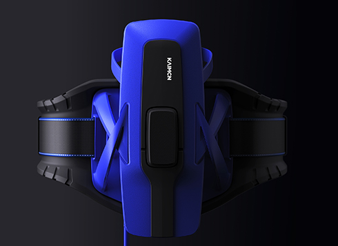 "Effortless" Exoskeleton Wear: Unleash Ultimate Freedom in the Sea
"Unfelt Wearability" & "Bionic Power" redef ...
-
After VR panorama delivery, why does the mobile view drift and why do hotspots misalign—which step usually hides the problem?
Date: Sep 20, 2026 Read: 4
-
Park plaza and street greening: tree crowns look thin up close—switch to 3D models first or unify leaf color first?
Date: Sep 19, 2026 Read: 9
-
WebGL product 3D display: metal and glass keep looking like plastic—bake environment maps first or use real-time reflections to avoid rework?
Date: Sep 18, 2026 Read: 15
-
Mini Program 3D display: the product goes black when rotated to the back—is the issue usually in baking or lighting layout?
Date: Sep 16, 2026 Read: 18
-
When a 3D bird's-eye rendering looks like a sandbox model instead of a real aerial photo, is the problem usually the camera or the scene props?
Date: Sep 15, 2026 Read: 23